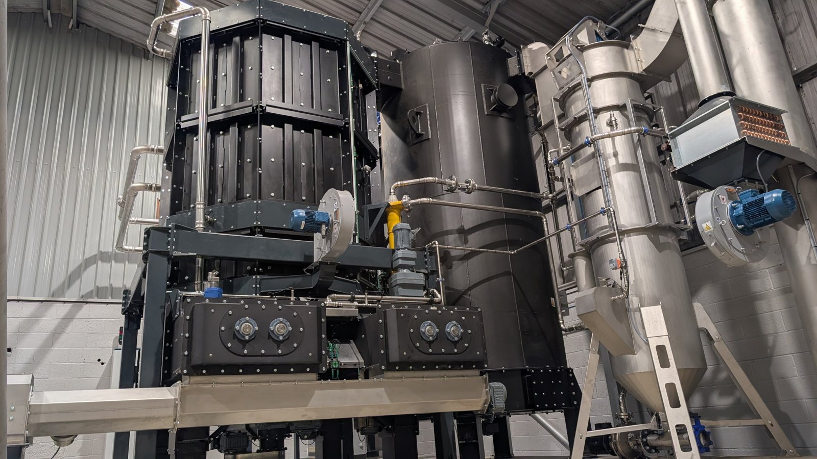
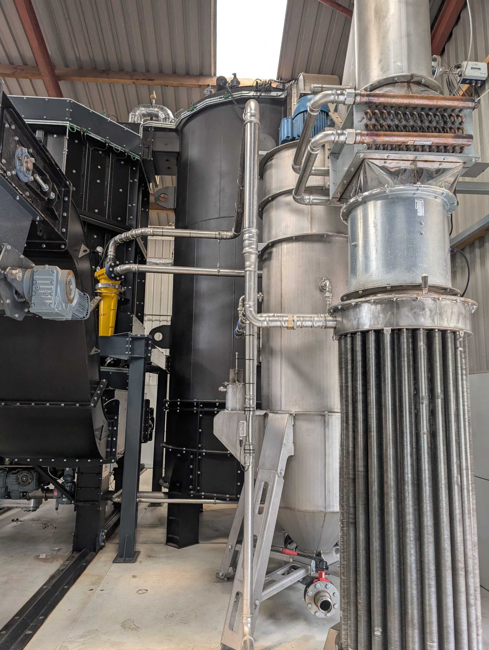
Plants in the ground.
A register, not a gallery, in commissioning order. A further four plants for another customer are in the pipeline.
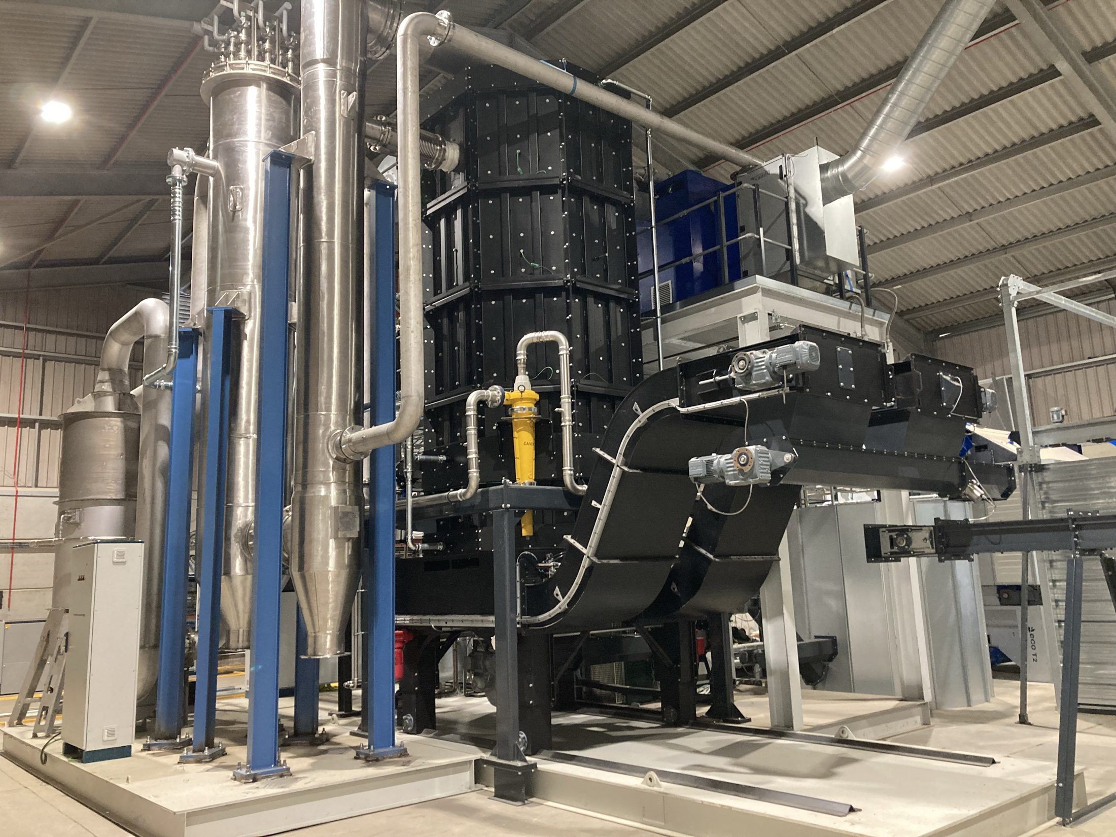
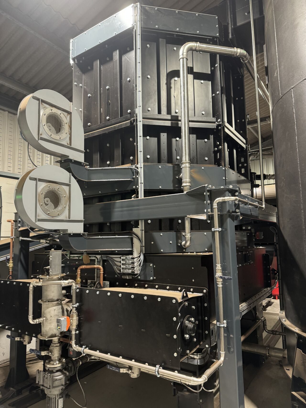
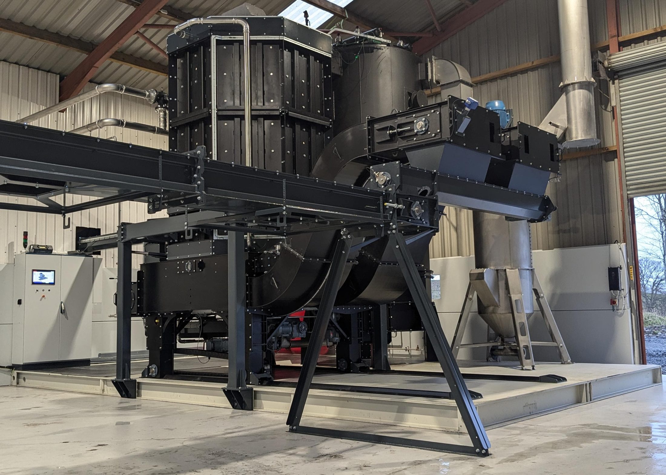
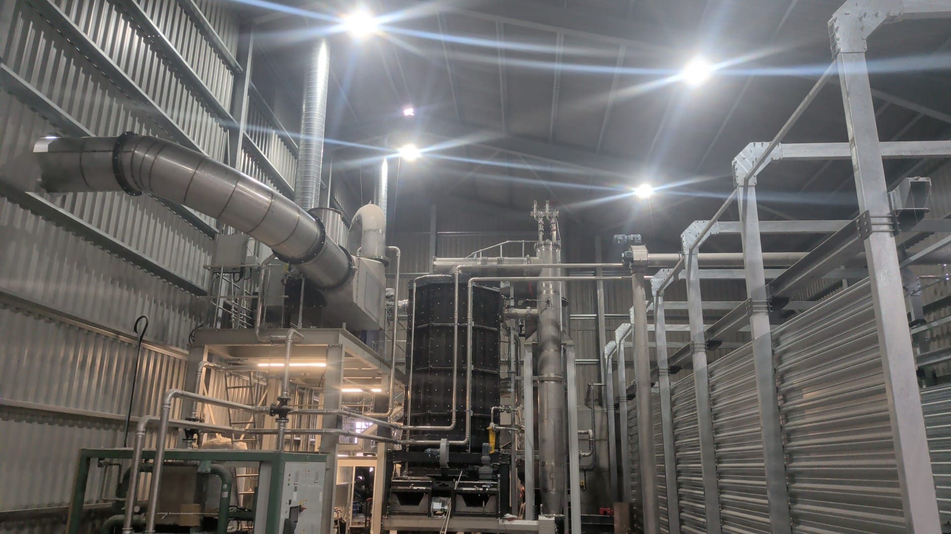
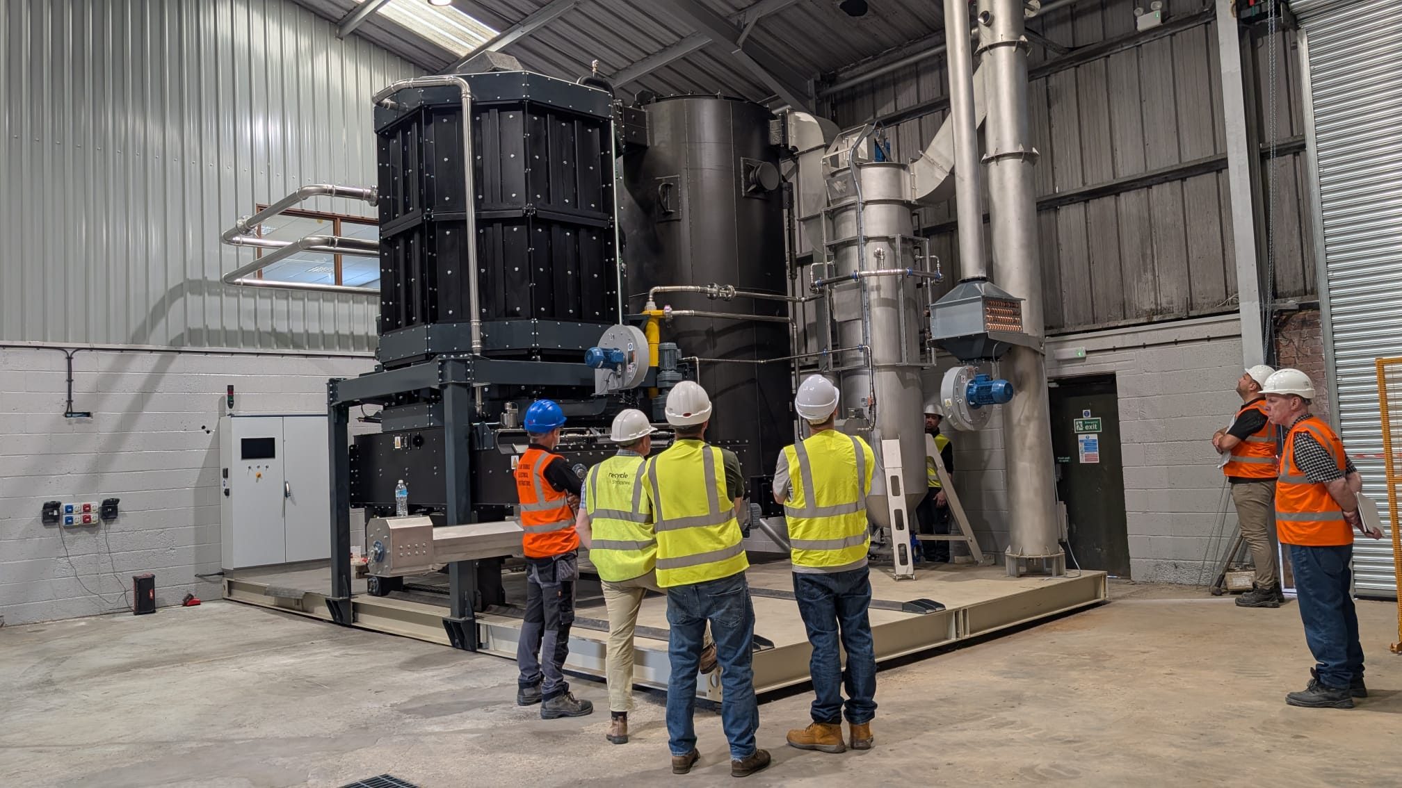
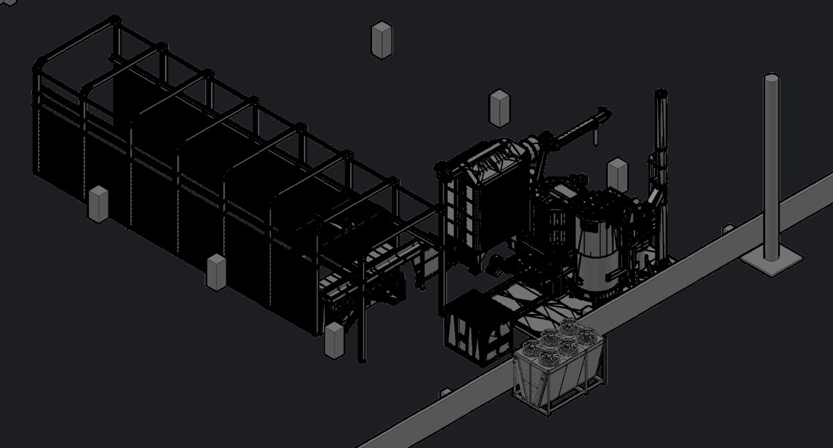
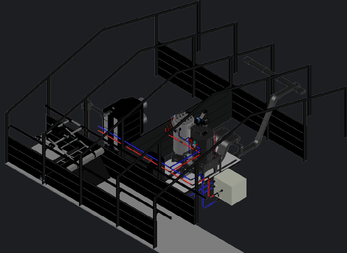
The kit that makes it a plant.
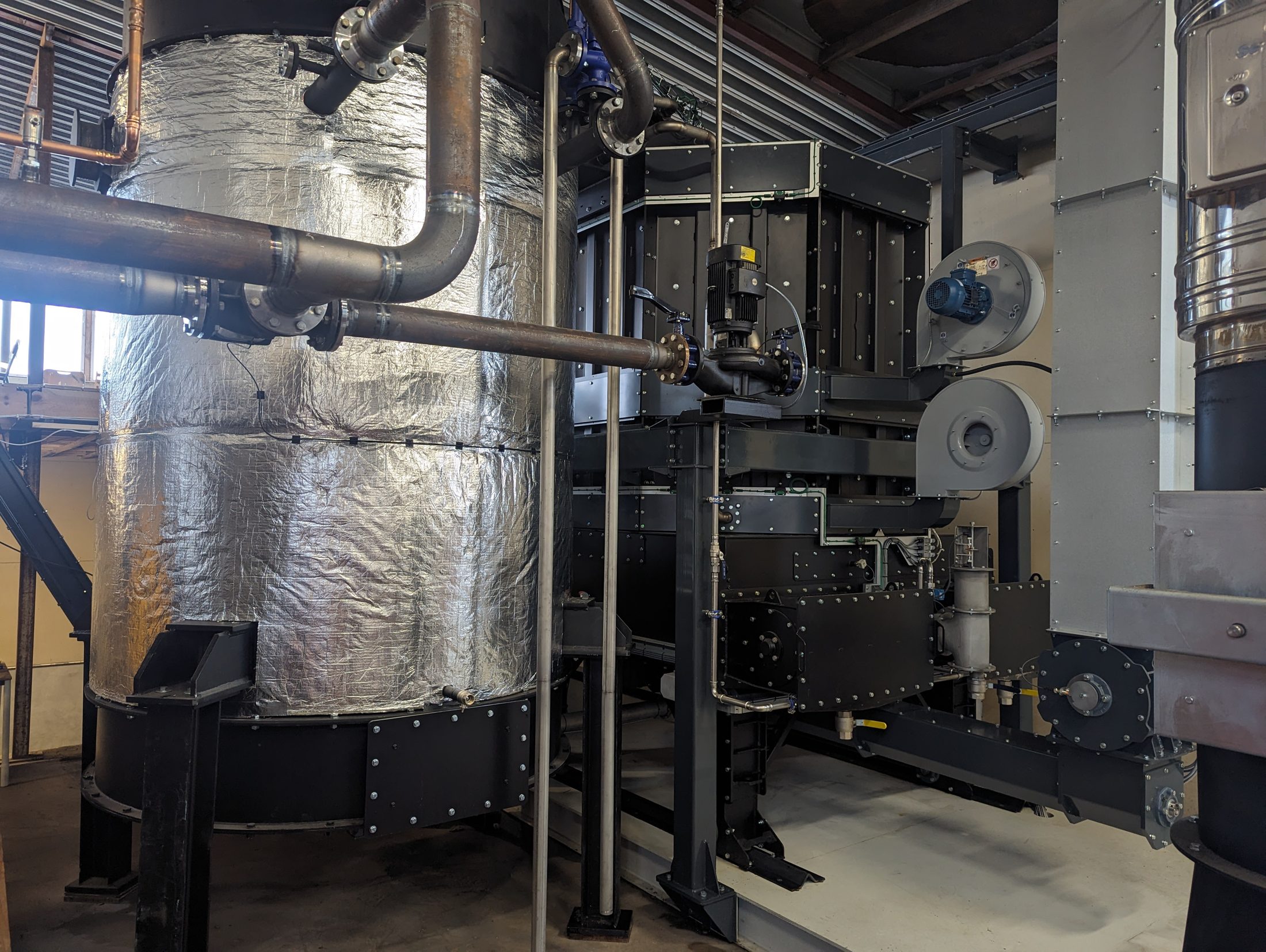
A C1000 arrives as one system. Woodtek designs and builds the three pieces of equipment around it in the same factory: the dryer that conditions the chip, the TopLoader that feeds it, and the wet scrubber that cleans the exhaust. All three are supplied together or on their own, on the same controls, by the same engineers.
Scrubber.
Woodchip in wet.
Woodchip out ready.
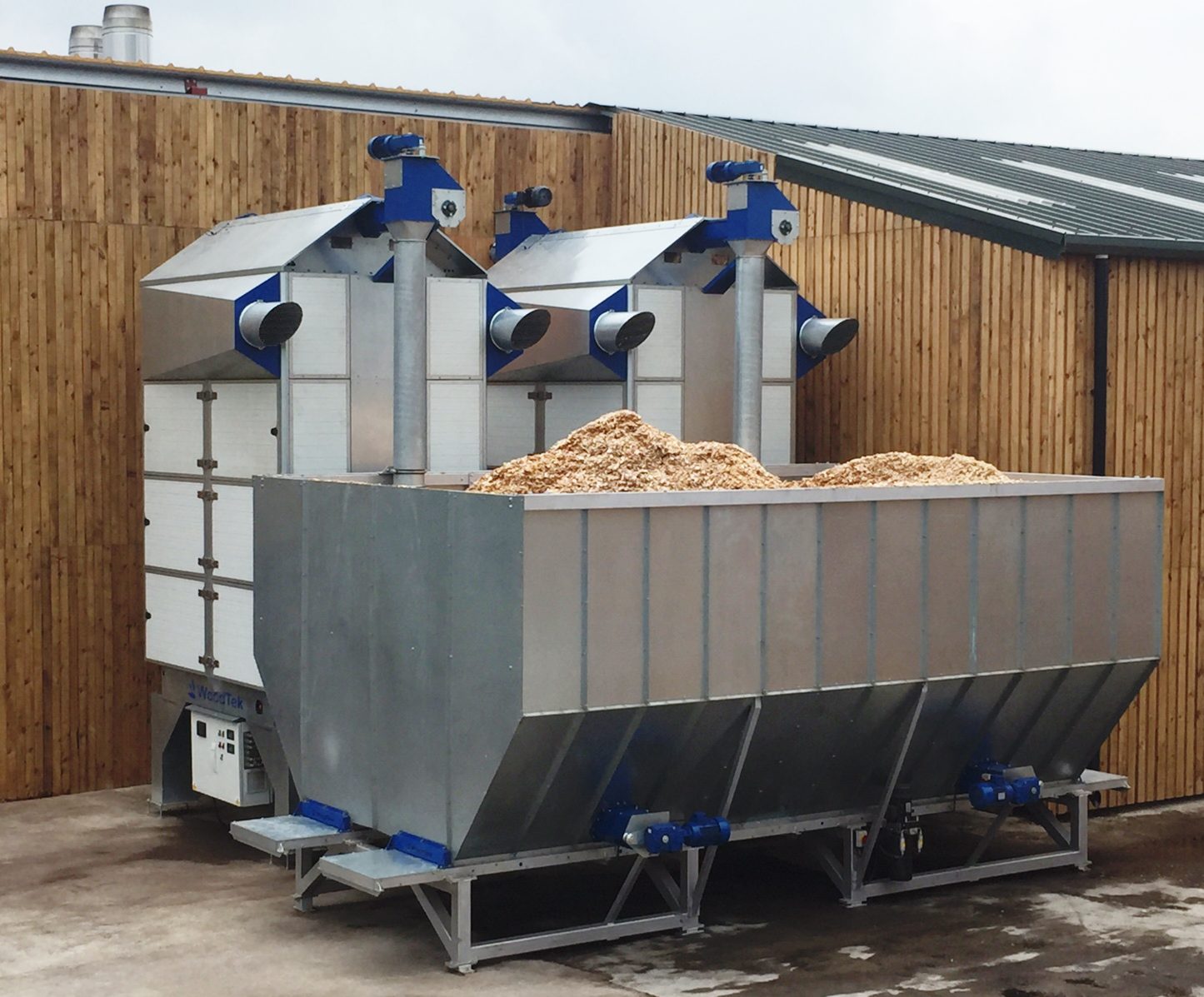
The Eco T4 Plus is a continuous-flow column dryer, the largest in the Woodtek Eco Compact range, with over 160 installed across the UK and Europe. Wet chip goes in the top, warm air passes sideways through it, and dry chip comes out the bottom at the moisture you set. Four stacked modules form five vertical columns: two carry the chip down, three carry the air across. Because the air passes through the chip rather than along it, the footprint stays small for the amount of drying it does.
The exhaust air leaves through the cold, wet chip at the top, which pre-dries the incoming load and filters the dust out of the air on its way out. Throughput is set by rotary valves at the base of each column; the PLC adjusts their timing against inlet and outlet air temperatures and a moisture sensor on the dried product, and holds the output steady. With a C1000, the drying heat comes from the machine's own flue gas through a heat exchanger, so the plant dries its next load with the heat from its last one.
40 to 55% moisture
15 to 25%, set per project
C1000 flue gas, biomass boiler or other
Below 105 °C, far below chip ignition
250 mm augers, discharge up to 8 m
T1, T2, T2 Plus, T4, T4 Plus
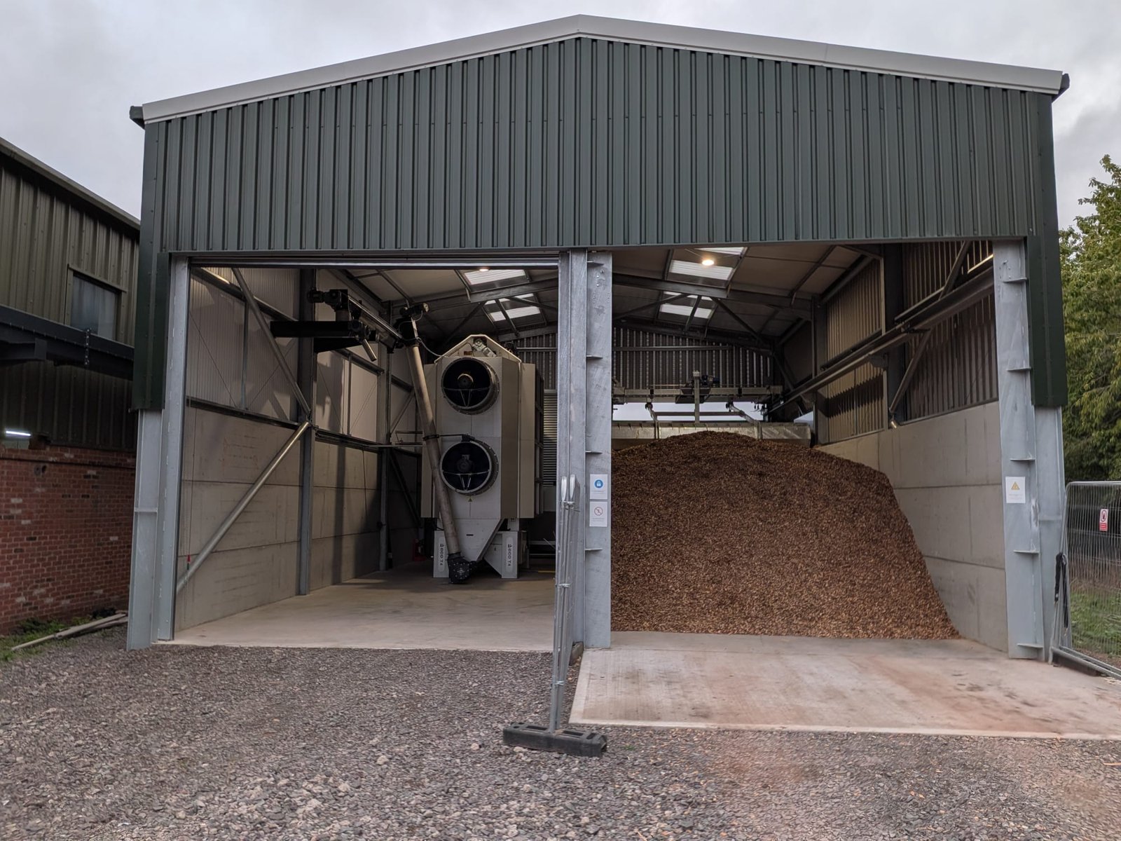
Tip the chip in the bay.
The plant does the rest.
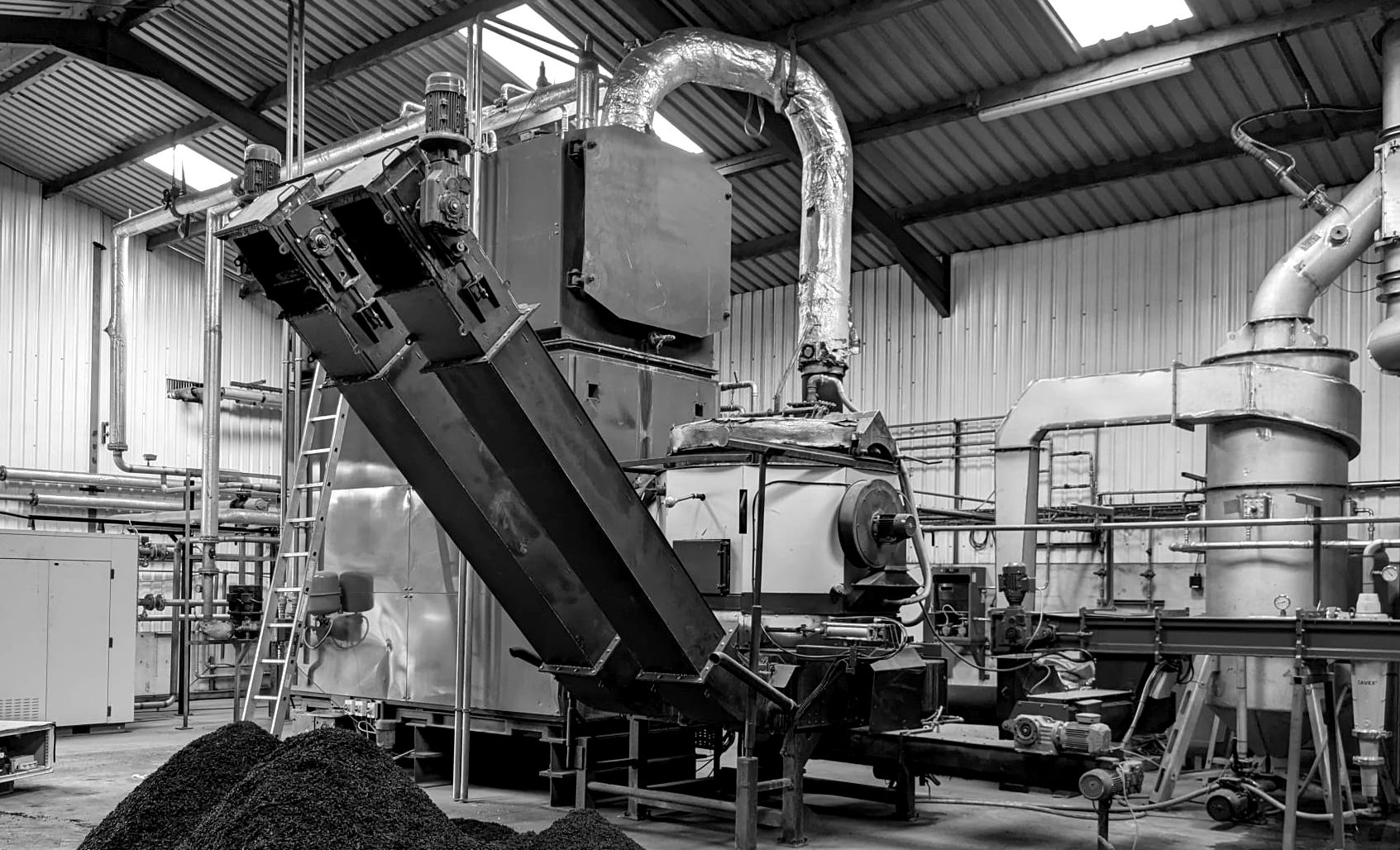
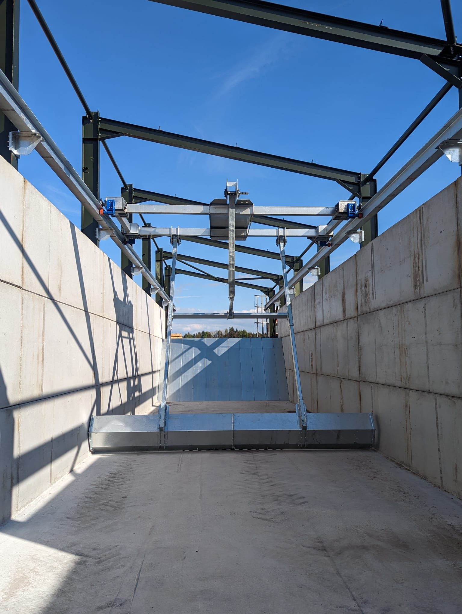
The TopLoader is an overhead carriage that runs on a track the length of the fuel store. When the hopper at the end of the bay asks for material, the carriage travels to the far end, lowers a winch-mounted drag arm into the pile, and scrapes the chip back along the floor into the hopper. Augers lift it out onto the discharge conveyors and on to the dryer or the C1000. Then it waits until it is asked again.
That is the whole job of feeding a plant, done without a loader driver: fill the bay with a wheeled loader when it suits, and the TopLoader works the pile on its own, around the clock, from its own control panel. Position sensors, end-of-travel limits and emergency stops at both ends of the carriage bring it to a safe state if anything is out of place, and fixed perimeter guarding keeps people out of the bay while it runs. An optional screening table takes oversize and contamination out of the stream before it reaches the machine.
Unattended, demand-driven from hopper level
Single bay, sized to the project
Indoors or under a roofed fuel store
400 V three-phase, own control panel
UK machinery regulations, UKCA marked
Shaker screening table
Heat out first.
Then the gas is washed.
Every C1000 is fitted with a wet scrubber on its exhaust. After combustion, the flue gas gives up its heat in the heat exchanger, then enters the scrubber in a cyclonic flow and is atomised with water. Particulates and the soluble gases, including SO2 and HCl, are washed out before the gas reaches the stack. The water recirculates continuously; a hydrocyclone separates the solids and sludge into the quench base and sends clean water back to the nozzles.
The scrubber, its pump and fans, and the stainless steel stack all run from the C1000 control panel and are watched by the same SCADA: water level, scrubber flow, hydrocyclone and stack temperature are monitored and interlocked, and the exhaust fan holds the furnace under a steady negative pressure so nothing escapes the gas path. It is not an add-on. It is the reason the plant runs cleanly in a shed next to a farmhouse.
Particulate, SO2, HCl
Combustion, heat exchanger, scrubber, fan, stack
Negative, 50 Pa target, fan controlled
Recirculated, hydrocyclone cleaned
Stainless steel, unpressurised
Integrated with the C1000 SCADA